Operational Protocol EEG-fMRI
EEG/fMRI
Topic |
Sub-Topic |
Primary Contact: Haidee |
Primary Contact: Hadi |
|---|---|---|---|
User Training |
Prepare and update training material: Operational protocol |
X |
|
User Training |
Train new EEG/fMRI users and provide access to lab |
X |
|
Data acquisition |
Acquire EEG/fMRI data when needed and clean the cap |
X |
|
CTP Administrative |
Budgeting |
X |
|
CTP Administrative |
Monthly report |
X |
|
CTP Administrative |
Risk assessment |
X |
|
CTP Administrative |
Usage and usage prediction |
X |
|
CTP Administrative |
SOP, SOP emergency |
X |
|
Faculty Administrative |
Elaborate consent forms template (with EEG/fMRI guidelines) |
X |
|
Faculty Administrative |
Explanations and queries about the lab |
X |
|
Experiment design |
Testing experiments and debugging |
X |
|
Lab space |
Ensure availability of Gel, syringe, earstick |
X |
|
Lab equipment and maintenance |
Ensure operational state of equipment |
X |
|
Lab equipment and maintenance |
Maintenance of the systems and troubleshooting |
X |
|
Data Analysis |
Maintain processing pipelines and provide MEG data analysis results |
X |
|
Equipment upgrade |
Upgrade, buy extra caps or auxiliary hardware |
X |
|
User Training |
EEG/fMRI demo |
X |
Standard Operating Procedure (SOP) for BrainAmp MR Plus EEG System
- Document ID:
CTP_MRI_001
- Issue:
0.1
- Author:
Haidee Paterson
- Reviewed by:
Osama Abdullah
- Location:
A2, GF, 014
—
Scope of Document
Basic operating procedures for the Siemens 3T Prisma MRI Scanner located in A2 Building.
Emergency Contacts
Role |
Name |
Contact Details |
|---|---|---|
MRI Physicist |
Osama Abdullah |
056-6793378, oa22@nyu.edu |
MRI Technologist |
Haidee Paterson |
050-8218598, hp42@nyu.edu |
MEG Scientist |
Hadi Zaatiti |
056-2754921, hz3752@nyu.edu |
Facilities Management |
Contact Security Desk |
EFS Helpdesk: 02-628-8888 |
—
Components of the BrainAmp MR Plus System
Inside the MRI Scanner Room
Amplifiers - 2 x BrainAmp MR Plus (32 channels each).
PowerPack - Portable and secure power source for amplifiers.

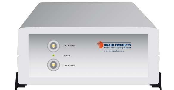


Important
- Ensure that the amplifiers are charged up before each data acquisition
Two amps connected to battery power supply and also to the Syncbox through fiber optics.
Battery power supply must be charged after each experiment
Recording computer is connected via two USB cables to the Syncbox
Electrodes and Cap: 2 x BrainCap with ECG electrode (56cm and 58cm)
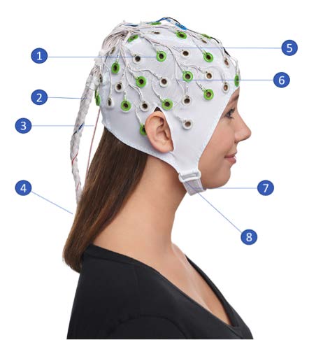
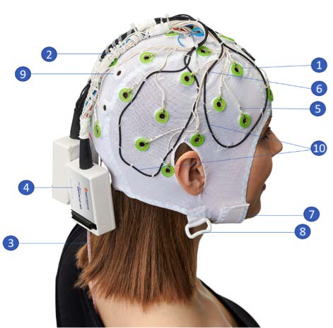
- Multritrodes for MR:
Sintered Ag/AgCl sensors.
- Cable tree bundled tightly.
All lead wires are bundled tight together as they leave the cap.
- ECG electrode with sheath protection.
Covered with a plastic sheath to prevent the cable touching the skin.
- Connector box
with current-limiting resistors.
Name labels on every electrode for easy recognition
Electrode cables are routed on the outside of the cap and secured to avoid loops and cable movement
Chin strap.
Loop for chest belt (belt not included).
Outside the MRI Scanner Room
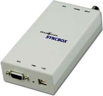
Syncbox: Extension box for phase sync recordings.
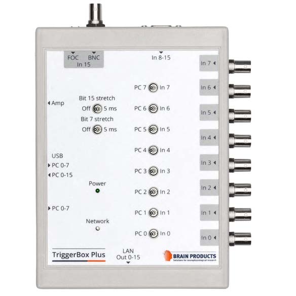
2. Triggerbox Plus: The TriggerBox Plus helps to handle and merge triggers arriving from different sources.
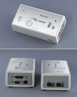
USB 2 Adapter (BUA): The USB 2 Adapter (also known as BUA) serves as a USB interface to connect any BrainAmp amplifier with the recording computer.
—
Safety Considerations
- System Users
All simultaneous acquisition of EEG and fMRI is performed within the MRI environment in the presence of a powerful magnetic field (3 Tesla)
All MR safety rules prescribed by the MRI radiographers/physicist must be observed at all times
All people involved in using the BrainAmp MR plus in an MR environment must an MR authorized person or MR operator or be supervised by the aforementioned
Simultaneous EEG-fMRI acquisition requires adherence to MR safety rules.
Only MR authorized persons or MR operators are permitted to operate the system.
- Product Labeling
Equipment labeled MR unsafe must not enter the MRI scanner room.
Only use MR conditional or MR safe equipment.
All components of the MR series of amplifiers carry a label related to their safety properties in the MR environment.
Equipment that is labeled as MR unsafe must not enter the MR scanner room.
Only use MR conditional or MR safe equipment in the MR scanner room.
All the EEG equipment in the MR lab has been labeled appropriately and must be strictly adhered to.
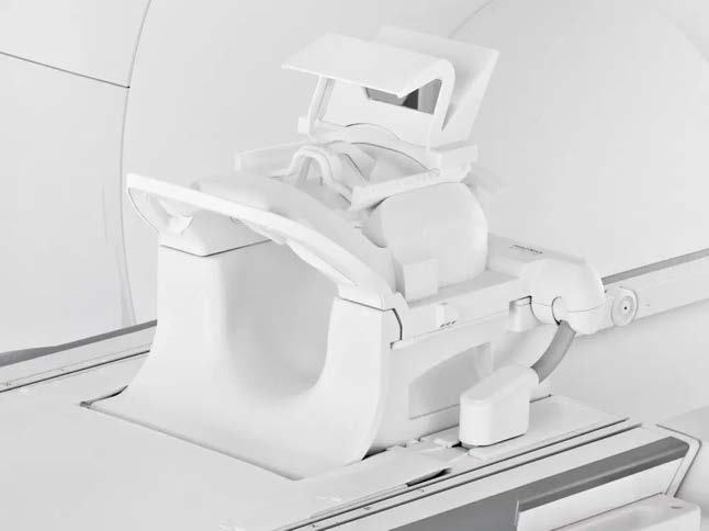
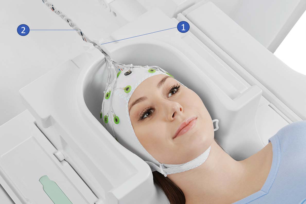
Head Coil for EEG-fMRI - Use the Siemens Head/Neck 64ch coil for proper cable routing.
Protecting the Amplifier - Prevent eddy currents and RF heating by following setup geometry and approved MR sequences.
—
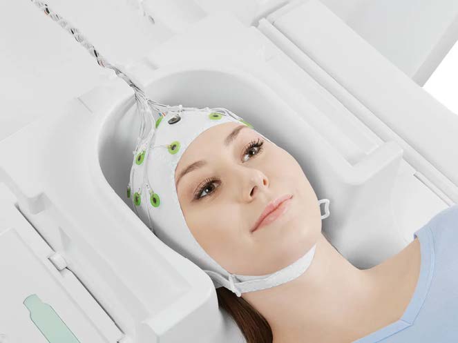
Capping and Impedance Preparation
Preparation of BrainCap MR
Perform all preparation outside the scanner room.
The recording computer can be put in the EEG mockup room to prepare participants prior to an experiment
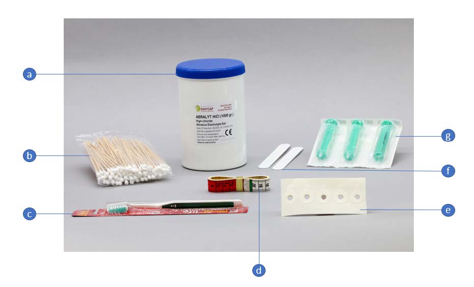
- Required materials:
BrainCap MR
BrainAmp system, USB2 Adapter
Preparation kit (Abralyt gel, cotton swabs, toothbrush, measuring tape, washers, syringes).
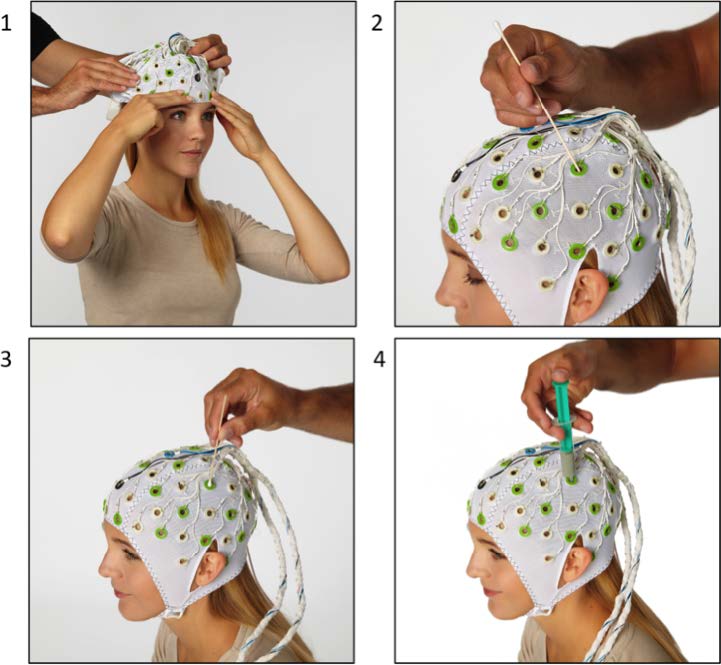
Positioning the Cap
Measure head circumference and choose an appropriately sized cap.
Position the cap starting from the forehead, ensuring Cz is centered.
Adjust electrode positions (Fp1/Fp2 above eyebrows).
Filling Electrodes
Push hair aside using a cotton swab.
Degrease skin with alcohol.
Apply Abralyt gel and gently abrade using the cotton swab.
Fill the space between skin and electrode with gel using a syringe.
Capping: every electrode must be well gelled (we cannot just use the electrodes we need) in an FMRI environment
- Impedence check
After setting up the scanner interfaces, the EEG cap was prepared, and we checked the impedance values of each electrode. Each electrode should be below 50 kOhm for EEG-fMRI recordings.
It is recommended to record some data outside of the scanner room. This can be used to check the quality of ECG signal and check for strong R peaks. In this data set, strong R peaks are visible.
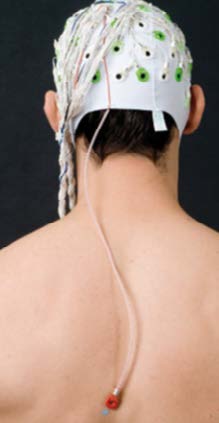
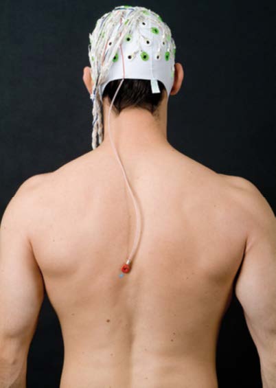
Positioning the ECG Electrode
It is important to place and gel the ECG electrode correctly on the back of the participant. The measurements from EEG electrodes will have ballistocardiogram (BCG) artifacts, the ECG electrode data is used to remove those artifacts in pre-processing steps.
Degrease the skin and attach the ECG holder using adhesive washers.
Place the ECG lead along the paravertebral line.
Ensure the lead is not taut and allows head movement.
—
Cleaning the BrainCap MR
Soak the BrainCap MR in lukewarm water for 10 minutes.
Gently clean electrodes with a soft toothbrush.
Use mild agents like baby shampoo if necessary.
Rinse thoroughly and remove all cleaning residues.
Pat dry using a clean towel and allow to air dry on a rack or dummy head.
—
EEG/fMRI system settings
At NYUAD, the Siemens trigger box from the scanner is on Toggle Mode.
The Recorder software settings on the EEG data acquisition computer is set to match the Siemens setup. In Recorder under Amplifier → Digital Port Settings set enable Bit15 and check both active The file BP_Onboarding_initial_test_toggle_24-09-2024.eeg was recorded with this trigger configuration. It results in T_on then T_off marker pattern for every TR.
This setting, will show T 1_off and T 1_on where the time difference between two consecutive ones corresponds to the TR. The default setting on BrainProducts is to have an R128 every TR, but this will not be the case for the setup at NYUAD.
Data acquisition process
The protocol describes the data acquisition process.
Activation of the product
The NYUAD MRI lab owns one permanent licenses for each of the three software BrainVision Recorder, BrainVision Recview and BrainVision Analyzer.
The licenses are on USB dongles, ensure that the USB dongles are plugged in into the recorder or analysis laptop
Software stack
BrainVision Recorder: data acquisition software that connects to the amplifiers and cap
BrainVision RecView: NA
BrainVision Analyzer: post-processing software for artifact removal, filtering and so on
Typical EEG-fMRI dataset structure
An .eeg file: raw data from the electrodes.
A .vhdr or .xhdr file: a header containing metadata on parameters and sensors.
A .xmrk file: contains markers with their time (can be opened in a text file).
Example of such datasets are present on NYU-BOX. Demo dataset has been provided by BP and are available on the recording computer:
In the S1-EEGfMRI dataset, at some point in time we can see the gradient artifacts
Some EEG-fMRI jargon: history is the sequence of analysis steps and each step is a node
BrainVision Analyser is used to perform analysis of the data after acquisition
External environment noise
Static field recording is important to allow removing the magnet noise (even when we are not using fmri) ideally we record first a lot of static field data until we understand the artifacts, then for each experiment we record atleast 1minute of static field data for the movement artifacts.
Collect EEG data in a static field to identify artifacts and remove them in post-processing
This involves collecting EEG data while the participant is in the scanner but not doing any task
Data acquisition protocol
T1 image of participant is needed (if source reconstruction will be performed)
Setup your experiment on the MRI stimulus computer to land on the Introduction Page of yoru experiment
- Setup BrainVision Recorder
Open the BrainVision recorder software in administrative mode
File -> Open Workspace, choose a workspace [TODO: Add name of default workspace here]
Outside scanner data acquisition and ECG sanity check
After the subject is gelled, impedence are checked and before they enter the MRI scanner room, ensure that: Each electrode should be below 50 kOhm for EEG-fMRI recordings.
Data must be recorded outside the scanner room to check for the quality of the ECG signal.
Check for strong R peaks. In this data set, strong R peaks are visible.
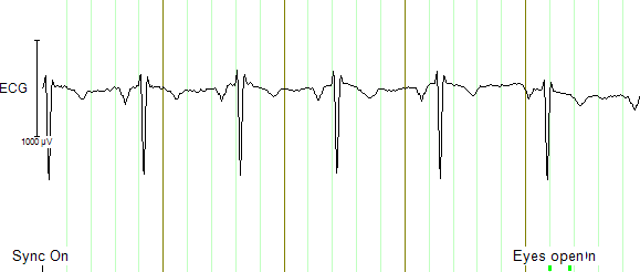
Strong R peaks on ECG electrode can be visualised as a sanity check before entering the MRI scanner room.
Experimental data can also be collected outside of the scanner for sanity checks
- To summarise, using the EEG-fMRI system data can be collected:
outside of the MRI scanner room
in the static field
during the fMRI session
This data can be used to compare the signal to noise ratio across different testing conditions
Static Field data acquisition
Prior to activating the fMRI gradient coils, make sure to collect a duration (ideally 2 minutes) of the static field
The static field data will be used for artifact correction in the processing pipelines
Helium Pump Noise:
Components around the 50Hz frequency should appear in all channels.
The helium pumps cannot be turned off during an experiment.
Ventilation System:
Usually causes a higher peak at 50Hz in FFT, with more spread-out noise across high-frequency components.
Markers and Timing Verification:
The marker verification allows us to see if any TR’s are not being marked correctly
Marker Verification needs to be downloaded separately to the BP software
If max and min in marker verification are very far apart, it means a marker is missing
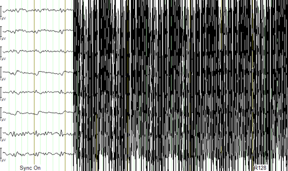
Gradient Artifact:
Occurs during fMRI data acquisition (while acquiring volume).
In Analyzer, use average artifact subtraction to remove the gradient artifact.
First we need to check that the EEG data is synchronized with the scanner clock (Sync On is the MRI scanner clock sync signal)
We need to have the R128 markers (T1 volume markers)
Gradient artifacts changes with channels
Movement and gradient artifact:
Gradient artifacts will change with the movement
We use the sliding average to account for movement artifacts
Stimuli shouldn’t match the time markers
Below is an example of gradient artifacts
Testing and debugging
Simulated amplifier environment
A simulated environment can be used to perform tests and debugging.
In BP Recorder:
Go to configuration, then select amplifier then select simulated amplifier
Create a new workspace and select data to be played back
To choose a simulated environment for EEG signals
Configuration -> Select Amplifier -> Simulated Amplifier
Then Test Signal, This should show you sinusoidal test signals